Posts

Showing posts with the label Fabrication

A slicker shifter

Image
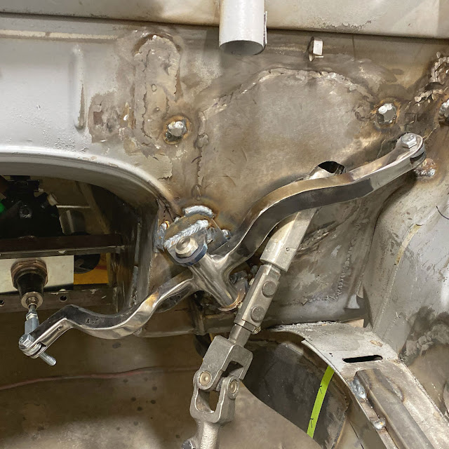
 Wow.  Almost 6 years ago I posted about the shifter mechanism I designed to adapt the stock automatic shifter for EV use.  In those 6 years my CAD abilities have improved dramatically and I've upgraded my 3D printer to a Bambu H2D.   I was never happy with the feel of the detents of the first version so I set out to improve it. Basically, I used off-the-shelf threaded ball-spring detents and slick UHMW plastic to eliminate the inconsistencies of the offset bearing design from before.  The new design is better and described in the video below.

Turning up the Heat

Image
 After a couple years of lost focus, I'm starting to make progress again.  One area that I've been undecided about has been Heating, Ventilation, and Air Conditioning (HVAC).  One main decision to make is whether to use the original heater core and A/C evaporator and blower fans or to go with an aftermarket unit.  The other is whether to add cabin heat at all.  I know I want/need A/C but in Southern California do I really need heat?  I didn't add heat to the silver CSE and Alex has been complaining about how cold it gets. I made a list of pros and cons for and against the stock heater/ac and in the end decided on aftermarket.  And heat.  I also decided I'd add heat to the silver car, which will further delay my build. I used the Restomod Air Vapir 2S in the silver car.  They've since come out with the Vapir 3S, which has floor heating and better defroster duct design.   We're also using that unit in Sam's customer build but Bre...

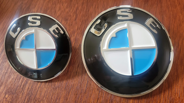
We really don't need any stinkin' badges. But they're awesome!

Image
My priorities are all wrong.  The car still needs a restoration and at the moment isn't even moving under its own power but I got side-tracked.  In my defense, this all started over two years ago, when I had more momentum on the project.  And it isn't uncommon for auto restoration projects to start with parts accumulation.  Often they end before completion but I'm hoping that's not the case here.  But I digress (again).

Better battery Box

Image
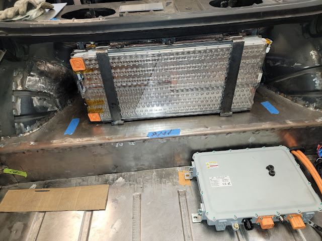
Picking up from " Danger Low Voltage! ".... After the batteries drained while sitting I decided to make some improvements to the battery box.  The acrylic see-through top was neat but it was unnecessary to see through the sides of the " aquarium " and the acrylic panels weren't very strong and cracked easily so I decided to change to aluminum everywhere except the top.  

Danger! Low voltage!

Image
Two and half years of neglect haven't been kind to my batteries.  While I was finishing up the silver car, my car just sat in the garage.  Actually, I pirated some fuse box parts from it use on the silver car so it wasn't even drivable any longer.  When I finally got around to working on it again, I relocated the BMS from the ill-conceived "bubble" into the trunk area.  But when I tried to test the BMS wiring, I found that all my batteries were well below desired voltage.  As a result, the BMS refused to charge the pack.

Butt ugly bumpers no more

Image
In my humble opinion, the BMW coupes were designed for thin chrome bumpers.  That's how they were originally drawn and built in the guise of the late 60s 2000 CS coupes.  When the larger 6 cylinder engine was installed, BMW put rubber strips and bumper overriders onto the bumper, ruining the clean look.  Even worse, US safety requirements forced BMW to pull the bumpers out away from the body to absorb 5 MPH bumps without damage.  Practical perhaps, but ugly.  Butt ugly.

Cardboard to CAD

Image
I discussed how I was able to gain clearance for my hood and battery box in the Good Under the Hood post but now I had to turn my attention to holding it up when open.  The factory support is a large complex torsion tube that runs the entire width of the engine compartment.  Because it goes across the entire engine compartment it would hit my battery box.  Plus, it is complex, dangerous, hard to paint, etc. and Paul had already figured out the geometry of switching to modern gas struts instead. Original hood prop system has torsion springs in a tube with arms (all the black stuff) Paul's car swapped to simple, lightweight gas struts I didn't love the welded brackets on Paul's car so I made a cardboard template to locate the pivot point and used that to make a model in CAD.  Instead of requiring welding, m...

Good under the Hood

Image
When I went to install the hood it wouldn't close.  One of the underhood braces interfered with the battery box.  Some surgery was required.  We bolted a brace to the hood so that the shape wouldn't be altered and then cut out a portion of the brace, leaving as much depth there as possible to maintain strength.  We took the cut out portion and flipped it upside down inside the void to reenforce the area and then filled it with some crumbled up aluminum foil.  We reinstalled the hood and closed it to make an impression in the foil.

Plugged In

Image
The onboard charger and battery management system have been in the car for a while but until today I had no way of adding electricity to the car.  I bought a J1772 receptacle a while back but hadn't got around to fabricating a way to mount it to the car.  

Battery Box Assembly Line

Image
Building a box to hold batteries sounds so simple.  It isn't. The batteries have been in and out of my front box many times now.  The latest reasons for disassembly were to relocate the BMS and plate the buss bars .  While plating, we decided to do the buss bars in Paul's car also since the battery box is out of the car while the car is being painted. My box on the left, Paul's on the right It is interesting to see the two approaches to battery fitment side by side.  Figuring out how to get 14 Tesla Model S battery modules fitted into a car designed for a gas engine and transmission is always the most difficult part of the EV conversion process.  The big rectangular batteries just don't want to fit into the curvy voids of a normal car body.

Get on the Buss

Image
The Tesla batteries need to be wired up in series to get to the 350+ volts necessary to operate the Tesla drive unit.  This means connecting them all together, one by one.  This could be done with cables but they'd have to be big cables because the drive unit can draw up to 680 amps under full throttle.  Cables that large are hard to work with so a better alternative is copper buss bars. 

BMS Bubble

Image
 My plan had been to mount the Battery Management System unit in the front battery box, in the void near the steering gearbox.  There is enough room and I had everything mounted when I realized there was a problem.  The Orion BMS 2 wiring manual clearly states:

Batteries in the Front, Batteries in the Rear

Image
With 10 Tesla Model S batteries up front, the job is only 71% done.  Because the Tesla drive unit needs a minimum of 272 volts to operate, and each module has up to 28 volts, there would be basically zero range with 10 fully charged modules.  Therefore, I need to add at least 4 more modules to the car somewhere to get any power or range.

We're hosed

Image
Hoses and brake lines are a challenge on this Frankenstein project.   Brake lines a combination of metric DIN bubble flares and ISO imperial double flares, with a super odd metric double flare on the Tesla master cylinder.  Plus, the original ATW front calipers have two redundant circuits so the original master had 5 ports.  The Tesla iBooster only has two.  And the original rear-mounted proportioning valve isn't practical with this new setup.

Suspended upside down

Image
 The rear suspension on a BMW 3.0 CS is supported by a rear crossmember that spans the width of the car, with the trailing arms mounted to clevises and the ends bolted to the car via rubber bushings. As mentioned previously in the Brace up Boys post, the crossmember is normally triangulated by the differential, which is mounted to the floor of the unibody, but I cut the diff mount off of the crossmember since it is in the way of where the Tesla drive unit needs to sit.  I then fabricated a new forward-facing member to triangulate the crossmember securing the the car.  Seemed good.

Stop, park, but don't roll

Image
The Tesla drive unit only has Forward, Reverse and Neutral. There is no Parking pawl. On a real Tesla there are electric worm-drive parking brake calipers that clamp down on the rear discs when park is engaged and stay there even when power is cut. Paul adapted those to his car because he was already fabricating new caliper mounts for his Wilwood upgrade but I'm sticking with stock brakes so that wasn't an option for me. Initially I thought I'd just flash a "Pull Hand Brake" type message on the dash app when you engaged Park but I found a better solution with a product called eStopp.

Pedalfest

Image
Bolting in an electric motor and some batteries is the easy part. The devil is in all the little details and decisions that need to be made to retrofit and replace needed systems like braking, power steering, cooling, HVAC, etc. The biggest hurdle yet to overcome is braking. Paul changed to Wilwood all around and devised a very clever mechanical solution (Fred) to change the direction of brake pedal travel and translate it into the transmission tunnel area where he mounted a hydroboost and Wilwood master in a backwards orientation. All that scared me and I had already rebuilt the stock ATE brakes before deciding to go EV so I had hopes of retaining stock braking all around.

Batteries, batteries, batteries

Image
The Tesla Model S battery system in my car consists of 14 individual modules (a real model S usually has 16). Each are 27 by 11.5 by 3.5 inches in dimension and weigh 55.8 pounds. They consist of 444 individual 18650 battery cells with 74 cells in each voltage cell and six of these voltage cells in series.

Brace up boys

Image
As mentioned previously, with the differential mount cut off the rear suspension I needed a new way to properly locate and secure the rear suspension member.  Tyler fabricated a long arm that welds to the front side of the member and travels forward into the old driveshaft tunnel.  Of course, I no longer have a driveshaft so that room is up for grabs now.  Using a motor mount from a Chevrolet Suburban, we welded a mount to the tunnel and bolted the new arm to the body via the rubber mount.  This is solid fore/aft but allows a bit of up/down swing if necessary.

Mounting the Motor

Image
Tesla motor, axles, and batteries have arrived. Unlike Paul, who is using the large Tesla motor, I have opted for the small rear drive motor. My goal is 300 hp and 200 miles of range. Not the 450 hp Paul is shooting for. 300 seems like plenty to me, given the stiffness (lack thereof) of our skinny pillared unibodies. Plus, the small motor sheds 100 pounds vs the large motor and is physically smaller, allowing more battery placement flexibility. Tesla Model S drive unit and axles.  I only need the inner CVs from the axles as they are much too long for the narrower BMW Like Christmas, 14 Tesla Model S battery modules, packed in foam The Tesla batteries are temporarily stored in a wooden rack The packing foam is useful for testing fitment of the batteries This first step in getting the drive unit into the car is to re-enforce the rear of the car to support it and provide the necessary mounting points. Plenty of space to work with now Strengthen those wheel tubs as much as possible We ...