Bolting in an electric motor and some batteries is the easy part. The devil is
in all the little details and decisions that need to be made to retrofit and
replace needed systems like braking, power steering, cooling, HVAC, etc.
The biggest hurdle yet to overcome is braking. Paul changed to Wilwood all
around and devised a very clever mechanical solution (Fred) to change the
direction of brake pedal travel and translate it into the transmission tunnel
area where he mounted a hydroboost and Wilwood master in a backwards
orientation. All that scared me and I had already rebuilt the stock ATE brakes
before deciding to go EV so I had hopes of retaining stock braking all around.
|
|
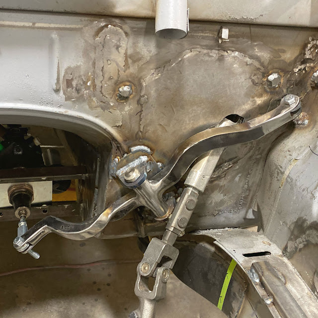
"Fred" - Paul's ingenious solution to moving the brakes out of the
engine compartment. Fred scares me, but works amazingly well.
|
But hopes are often crushed and there just isn't room in the engine bay for 10
Tesla Model S batteries and a brake booster/master. I contemplated manual
brakes, given all the regen braking I get for free, but sure-footed stopping
power is too important so I had to figure out a way to get power braking into
the car somehow. With some help from Matt at
https://www.powerbrakeservice.net/
we devised a system that has a simple single reservoir master on the firewall,
activated by the brake pedal that then pushes fluid to a slave cylinder that
then pushes on the Bosch hydroboost unit, as if it were actually the brake
pedal rod, which then pushes on the master cylinder. In order to get the
piston sizing all correct I had to ditch the stock master in favor of a
Wilwood dual unit. It only has 4 output ports, instead of the ATE's 5 so I'll
need to Tee the front lines to the dual hoses on the front calipers.

|
|
Complex slave cylinder to hydroboost unit to Wilwood master
cylinder. The idea is to put this anywhere handy (like the trans
tunnel) and run a single brake line from a small master cylinder on the
firewall to the slave cylinder here.
|
Before I could even get that far some work needed to happen in the pedal area.
The battery box encroaches on the area where the brake pedal rod normally
exits the firewall but the area for the clutch cylinder is open so I need to
mount the new "master" there. Of course, I don't want to use the clutch pedal
to slow the car (this isn't a Model T after all) so I sourced a pedal from an
e28 and did some machining and welding to fuse the two pedals together. But it
turns out that the e28 clutch pedal is about 1/2" farther to the left so I had
to move it in a bit to align with the hole in the firewall. This was all a lot
of work. The inner pivot had a spacer welded in the middle between the two
pedals that had to be machined off in the lathe and then the e38 pivot tube is
longer than necessary so that had to be milled down to the precise length so
that it is about 1mm than the inner pivot so that, when bolted to the car, the
inner pivot is held tight but the pedals are free to swing without any side to
side movement. When all done it works and looks fine (obviously it all needs
to be cleaned up) but the pivot tube was about 1mm out of true, making it hard
to fit the '73 style long bushings in. I actually only had the one long
bushing from the brake pedal so I had 3D printed a second one as a stand-in
until I could source an original Nylon bush but since they didn't fit
perfectly I was forced to opt for Plan B. The e28 pedal came with the smaller
split plastic bushings that just fit on the ends. These are more what I'm used
to in the old Chevrolets etc. and they fit and work perfectly (once we milled
another mm or so from the pedal pivot length) so that's what I'm going with.

|
|
Modified single-action brake pedal that can now exit out the clutch hole
|
When I say firewall I really mean the steering column bracket that is bolted
to the firewall and dash. We had already lopped off the stock brake booster
support tube and destroyed the nice new powder coating so I needed to blast
off the coating and seal up the big hole that was no longer necessary since I
won't be running brake or throttle linkage through there. Of course, I wasn't
lucky enough to have the ears on the new master exactly match the pattern of
the stock clutch master so I had to gusset and weld that up to make it strong
with the correct bolt pattern. I welded studs to the bracket so that
R&Ring the master doesn't require crawling under the dash to keep the
bolts from spinning. Once done, I have a brake pedal operating a small
master. A minor accomplishment but I didn't realize that the mounting
surface for the clutch master isn't perpendicular to the ground (the stock
clutch cylinder must have an angle to the ears) so the new master was tilting
down slightly. I don't think this would have any material effect on the
operation, other than preventing full fluid level, but it bothered me enough
that I had to fix it. And, as you'll learn in a bit, all for that work
for nothing.

|
|
Making a paper template to fill the old brake mount hole
|

|
| Hole welded up |

|
|
Gusset welded to bracket to hold small master cylinder
|

|
|
It fits in there nicely
|
The next step for braking would be to mount the slave/hydroboost/master combo
in the transmission tunnel area but I also need to fit the hydraulic pump into
that area so I sourced an electric power steering pump from an 02-06 BMW/Mini
and was trying to work out how to fit both pieces into the tunnel area, while
still leaving room to get to hose fittings, and most difficultly, how to route
the hoses/lines from the reservoirs down to the master/pump.
But... after doing all the work to adapt the small master cylinder to the
clutch side of the brake pedal I learned of an alternative approach that was
promising. Tesla uses an electric brake booster from Bosch called an iBooster.
It has a pedal sensor built in and sophisticated electronics to allow braking
by wire over CAN for Auto Pilot but some people smarter than me figured out
you can run it in"failsafe" mode with just a 12v input and you get power
brakes without vacuum or hydraulics. Best of all, it's a fairly compact unit
and there was a chance it could squeeze in between my battery box and the
inner fender, in roughly the normal location for a master cylinder, thus
obviating the need for any remote placement shenanigans.

|
|
The Tesla iBooster electric power brake unit
|
So I bought an iBooster from a wrecked Tesla and did a test fit. It's tight
but it will work. Now, I just need to cut out and throw away all that work
mounting the small master and modify the steering column bracket once again to
mount the Tesla iBooster and run a rod through the mount to the pedal.

|
| It'll fit |
With fabrication help from Brett, we built a custom "horn" out of sheet metal
to mount the iBooster. It is an amazing design -- super strong but very
lightweight. We TIG welded it to the steering column brace and to a
flange purchased from
EVCreate
in the Netherlands.

|
|
Welding the horn on the bench
|

|
|
The "horn" looks strange but works perfectly
|

|
|
A rare photo of me working on the car (I'm usually the one with the
camera)
|

|
|
One iBooster mounted and ready to go
|
In the meantime, there is one more pedal to setup. The throttle pedal is an
electronic potentiometer and there wasn't enough room between the steering
column bracket and the trans tunnel hump to fit it properly. I always look to
Paul's solutions first. He cut into the tunnel to make more room but I didn't
think that was necessary so instead, I opted to relieve the steering column
bracket a bit and bend it inwards to make room for the pedal assembly. I
fabricated a mount and now the pedal is perfectly situated.

|
|
Throttle pedal mount
|

|
|
Throttle pedal mount (hole allows access to stock steering column
mounting bolt)
|

|
|
We have both pedals now
|

|
|
Drive-by-wire throttle pedal assembly is really just a big potentiometer
|