Danger! Low voltage!

Two and half years of negligect haven't been kind to my batteries.  While I was finishing up the silver car, my car just sat in the garage.  Actually, I pirated some fuse box parts from it use on the silver car so it wasn't even drivable any longer.  When I finally got around to working on it again, I relocated the BMS from the ill-conceived "bubble" into the trunk area.  But when I tried to test the BMS wiring, I found that all my batteries were well below desired voltage.  As a result, the BMS refused to charge the pack.

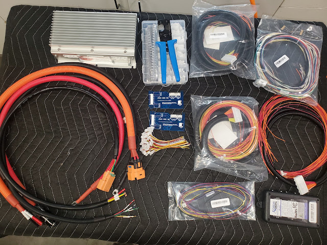
Between the two cars, I have a few Tesla batteries.

Therefore, I was forced to pull all the batteries out of the car and nurse them back to health by individually charging each one slowly.  Fortunately, they all came back to life and hold their charge well so I can reassemble the car again.

But this presented an opportunity to re-work the connections in the front battery box.  My original setup was less than ideal.  I thought there would be more room to work in the access hole at the rear of the box but there isn't.  I originally envisioned the HV cable connections, BMS, thermistor expansion module, HV fuse, and cell tap connections all living in the void in the front box but it wasn't practical.  There just isn't enough room to connect all the wiring.

Ampenhol 90 degree plugs, each keyed differently to prevent mixing up positive and negative

It took a while to find connectors designed for the large 2/0 gauge cabling

I moved the BMS and TEM to the trunk and now I'm changing the HV connections from cable lugs to Ampthenol HV posts and plugs.  I've also decided that the "fish tank" look isn't ideal for the front box so I'm fabricating aluminum side, front, and rear panels to replace the old clear Plexiglass panels.  This will offer more strength and a solid mounting location for the HV posts.  I designed the aluminum panels in CAD and had them cut out via Send-Cut-Send.

CAD design of front panel for battery box

I also got some new, high-quality high pin count connectors for the cell tap and thermistor wiring.  I didn't want these protruding from the box so I designed and 3D printed a recessed plug panel that cleans everything up nicely.

47 pin connector for cell taps and thermistors

Recessed panel bolts to rear of battery box

It was tedious work to pin all the cell taps and thermistor connections but I finally got it all done.  I connected all the batteries together in the rack and used the new wiring harness to connect them to the BMS.  I built a fake CANBus network and fired it all up.  

Labels, a printed reference, two different sized crimping tools, and a special pinning tool are all required to properly pin the new connectors

It was a tedious process

Each wire is labeled with shrink tube.  The small 22 gauge wires will not seat without the use of the pinning tool (pictured)

Everything connected in the rack

Lo and behold!  It all works perfectly.  The batteries have a proper, safe charge, the numbers all look great in the Orion BMS software, and even the thermistors are all measuring properly.

Every battery is in the 3.81 volt range, verifying the harness was built correctly


The thermistors are all reading 14-15 degrees C

I powdercoated the new aluminum battery box sides black and installed the new Amphenol High Voltage posts and connectors.  It is all look professional now but I don't see any reason to install it into the car again.  Once I've got the HVAC install all fabricated I will be ready to strip the car for paint.


Popular posts from this blog

Different strokes

We really don't need any stinkin' badges. But they're awesome!