Picking up from "Danger Low Voltage!".... After the batteries drained while sitting I decided to make some improvements to the battery box. The acrylic see-through top was neat but it was unnecessary to see through the sides of the "aquarium" and the acrylic panels weren't very strong and cracked easily so I decided to change to aluminum everywhere except the top.
 |
| Improved front battery box |
In addition, I never liked the way the HV cable connections were done. They were bolted to posts inside the box that were difficult and dangerous to reach. Also, the BMS bubble was a terrible idea that never worked so I had already relocated the BMS to the rear. But that meant that the cell tap connections up front were also less than ideal.
The first thing I did was slowly charge the batteries back up to proper voltage and monitored them over 6 months for any voltage loss. Fortunately, it was minimal.
.jpg) |
| Slowly charging two car's worth of Tesla batteries, one at a time |
I measured the old acrylic panels, drew them up in CAD, and had them laser cut by Send Cut Send.
 |
| Drawing of battery box front panel in Fusion 360 |
The most difficult part was the box that sticks on the left side to cover the end of the horizontal battery on top. It had to be TIG welded together and then onto the side panel without warpage and will minimal tolerances.
 |
| Measuring and planning for box to cover battery end |
 |
| Box all TIG-welded up to side panel |
 |
| Test fitment |
 |
Fits perfect
|
While in there, I decided to improve the battery cooling lines also. Originally, I had used brass fittings on the aluminum manifolds but can contribute to electrolysis so I switched to plastic (Nylon) barbed fittings. I also ran aluminum tubing in areas with difficult bends to prevent kinking of the hoses. This included lines up to the horizontal top battery, which fit better into the box mentioned earlier.
 |
| Aluminum lines to top battery allow tight tolerances and no chance of kinked hoses |
 |
| Lines run along top of battery box to manifolds in front |
 |
| All coolant lines connected with no brass components |
 |
| Of course I had to connect a pump and perform a leak test |
I sourced some high voltage connections from Amphenol (RADSOK SLP Series) for the HV cables and located them on the lower sides of the box. The connectors are keyed differently between positive and negative, preventing improper connection.
 |
| Connectors are correct of 0/2 gauge HV cables. They get hydraulically crimped. |
 |
| Each connector has tabs in different orientations to prevent incorrect connection |
 |
| Post mounts to box frame and panel |
 |
| Negative HV cable connected to post |
 |
| Connector posts are only available in a straight configuration so had to be mounted to sides of the box |
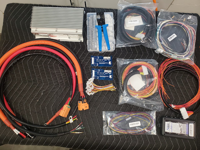
I also sourced some 47 pin connectors (TE Connectivty/ Deutsch HDP24-24-47SE-L017 and HDP26-24-47PE-L017 with 0460-202-2031 and 0462-201-2031 pins) for the cell taps and thermistor wiring. Wiring all the connections (60 cell taps, 20 thermistors, plus grounds) required a lot of up front planning and close attention to detail. It can get confusing assuring that the pins are properly aligned between the plugs and receptacles. Special tools are required to insert (or, in rare cases, remove) pins. It was a pain in the butt to wire up but cam out nicely when done.
 |
| 47 pin connectors |
 |
| I designed and 3D printed a recessed box to mount the connectors to so that they do not protrude from the rear of the box |
 |
| The back of the receptacle end |
 |
| The front of the receptacle end |
 |
| The front of the plug end. I numbered all the pins to assure I didn't get confused. |
 |
| The 3d printed recess and connectors test fit to the battery box |
 |
| Special tools required for crimping the pins and pushing them into the connectors |
 |
| I printed heat-shrink labels to keep track of which wire was which |
It was tedious work to pin all the cell taps and thermistor connections but I finally got it all done. Prior to final assembly, I connected all the batteries together in the rack and used the new wiring harness to connect them to the BMS. I built a fake CANBus network and fired it all up so that I could verify my cell tap and thermistor wiring was all correct.
 |
| BMS connected via new wiring |
 |
| Thermistors all look good |
Lo and behold! It all works perfectly. The batteries have a proper, safe charge, the numbers all look great in the Orion BMS software, and even the thermistors are all measuring properly.
 |
| Every battery is in the 3.81 volt range, verifying the harness was built correctly |
Once fitment and wiring was verified, I had all the panels powder coated black. Since the aluminum panels would conduct in case of an accident, I installed non-conductive phenolic barrier strips from a Tesla Model S around the edges of the inside of the box and installed weatherstrip to seal the box from water intrusion.. The end result is stronger, safer, and better looking.
 |
| All the panels ready for powder coating |
 |
| All wired up |
 |
| Phenolic isolation strips added for safety |
 |
| More phenolic strips along the top edges |
 |
| Front view |
 |
| Left side |
 |
| Notice how clean the welds are on the extension box |
 |
| Left Rear |
 |
| Connectors |
 |
| Right rear |
 |
| Top rear |
 |
| From the top |
 |
| Right front |

.jpg)