Shifting gears
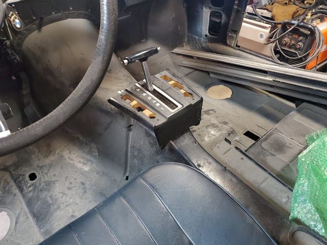
Gear selection in a Tesla drive unit is done electronically. That's why so many electric cars have gear buttons instead of gear levers -- there's nothing physical that needs to move. But, in trying to keep the original BMW aesthetic, I want to use the stock automatic transmission shifter to send signals to the Tesla drive unit.
To that end, I've been playing with CAD and 3D printing in an effort to adapt the factory automatic trans shifter to my needs. The trouble is, without the detents in the auto trans itself, the original shifter was a floppy mess. I also need a way to convert the mechanical motion of the shifter to electrical signals I can send to the Drive Unit Controller of the Tesla motor.
The original US auto shifter had gear indicator lights on the steering column so I figured I could repurpose the rotary switch bolted to the side of the old auto trans. If they could make it illuminate light bulbs then I could use it to send 12v signals to the Tesla. But I also needed detents to hold the handle in place so I devised a rotary unit comprised of three sandwiched plates with a round disc in between that had dimples on its edge. Then, a ball bearing and spring could push against the dimples, providing distinct stop points. Skateboard bearings held the D-shaft going through the disc. I'd then have to devise a linkage and lever system to make the shifter spin the shaft, similar to how the original gear selector shaft in the side of the auto trans operated.
It took a while to figure out how far down the shift arm I needed to attach the linkage in order to get the proper "throw" to match the movement of the plate -- but it works perfectly. For durability, I milled the slider out of aluminum and cut an aluminum plate for the back but ABS works well for the rest of it.


