Hooking up the first 10 Tesla battery modules for traction (High Voltage),
monitoring, charging, and cooling is a big job. As mentioned in the "We're Monitoring You" post, each set of cells needs to be monitored by the BMS to balance the
cells and prevent overcharging. They also need to be watched for
temperature when driving via the built-in thermistors and cooled via the
built-in cooling passages.
I started with the high-voltage side of things because that dictates where
everything sits in the battery box. There are a number of ways to
connect the batteries but I came up with one that terminates both the negative
and positive terminals in the "BMS Void" area of the box and can be connected
with solid copper busbars in every junction except one.

|
|
High voltage layout, terminating in void
|
I had purchased some really nice busbars from Electric Classic Cars, UK and
used them where possible but the odd layout of my batteries made in necessary
to fabricate some custom connections also. I purchased 3 feet of 1 1/2" copper
bar from McMaster-Carr and made three custom busbars. The Orion manual
states "do not use homemade busbars" and goes on to say "bare, unplated copper
busbars have been known to corrode or oxidize quickly, which can lead to high
resistance connections between cells resulting in reduced reliability."
All my busbars have bends to allow some flexibility and prevent transmission
of vibrations to the cell terminals and I will eventually have them chrome
plated and vinyl coated in the non-conductive areas to make them
"professional" but for now, they do the job.

|
|
Testing my first busbar -- 3 modules in series, all partially charged,
gives 63 volts, or 21 volts each
|

|
|
More busbars. Up close.
|

|
|
With all 10 batteries connected I had 210 volts. This is 21
volts per battery because they are only partially charged.
They go up to 28 volts each when fully charged. When the four
rear batteries are added to the system I'll have over 350 volts.
|

|
|
The only cable runs from the top battery (#7) to #8. 0/2 AWG wire
needs to find its own bends
|
Assembling my battery box is like a Japanese puzzle -- each battery must be
inserted in the correct order, with it's connections made, before the next
battery is slid in above.
Next up was to solder connectors to the BMS harnesses at the proper lengths
for the each cell tap. The cell taps allow the BMS to monitor the
voltage of each group of cells. To balance the cells, the BMS can shunt
off power from cells with higher voltages while charging the cells with lower
voltages. The thermistors allow the BMS to monitor the temperature of
the coolant entering a leaving each battery module.
Create a harness sounds simple but each battery requires 11 wires -- 1 cell
tap negative, 6 cell tap positives, and a positive and negative for each of
the two thermistors. Each run combines wires from the one of two BMS
harnesses and wires from the thermistor expansion module harness. And
both the BMS and thermistor expansion module are stingy with ground wires so
some have to be split and shared.
It took almost a week of evenings to get it all correct. I soldered
connections, labeled with printed heat shrink, wrapped in woven split loom,
and taped with Tesa tape.

|
|
The complete harness for the front battery box cell taps and
thermistors
|

|
|
Each run is labeled with heat shrink
|
|
|
The harness plugs into the 057 Tech cell tap boards on each Tesla
battery
|
I wish I could say that everything worked perfectly first time but alas...
Orion makes a harness checking tool but I don't have one. It measures the
voltage from each tap once the harness is plugged into the batteries but before
it is plugged into the BMS itself. I began testing by plugging the harness
into the batteries without the batteries connected via high voltage, just to
test the harness lengths -- and then I noticed smoke! Yikes! I
quickly unplugged the harness.
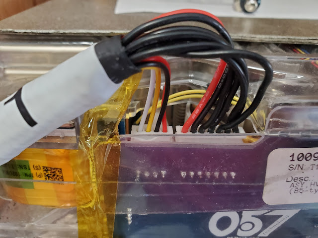
Further investigation shows a short on one of the 057 Tech cell tap boards but
I have yet to figure out why. Stay tuned.

|
|
Short on the #1 positive cell tap wire
|

|
|
Burned right through the PCB ribbon
|

|
|
Still a lot more wiring to do
|
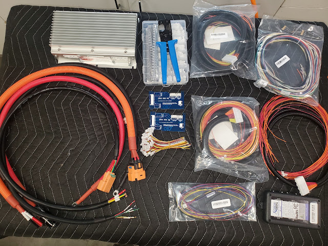
Unfortunately, that's just the start of the wiring projects.
There is the main power, CANBus, charger ready, etc harness for the
BMS, the current sensor BMS harness, cell taps and thermistor wiring for
the rear 4 batteries, power and CAN for the thermistor expansion module,
etc. And that's just up front. In back there's the J1772 plug,
the onboard charger, the DC/DC converter, the precharge controller,
contactors, etc.