The blog for conversion of vintage BMW 3.0 CS coupes to Tesla powered electric vehicles
Going Analog in a Digital World
Get link
Facebook
X
Pinterest
Email
Other Apps
-
You've read about the
fancy digital dash app I've written
that displays all sorts of information on a display in the hole that used to
belong to the tachometer. But that still leaves four other analog gauges
in the instrument panel: The speedometer, clock, fuel, and temperature
gauges. These are old school VDO gauges that just look proper and cool so
I want to make them all work with this new digital vehicle.
The instrument cluster with all analog VDO gauges in beautiful
refinished real walnut
The rear of the original VDO gauges
The clock is no problem. While young children may no longer be taught
how to read an analog clock, I know how and mine has been serviced with a new
quartz movement and works perfectly. Done.
The original clock, modified with quartz movement
I have a plan for the speedometer but haven't executed it yet. The idea
is to buy a
mechanical drive speed converter
with a digitally controlled motor that spins a short speedometer cable.
I will send speed messages to the unit from my Raspberry Pi dash app via
CANBus. But that can wait.
The original speedometer and odometer
Speedhut's Speedbox digital to mechanical speedometer adapter
In the meantime, I've been focused on the fuel and temp gauges. I'd like
to show range on the fuel gauge and the "most relevant" (i.e. closest to
critical) temperature on the temp gauge. I have both of these values
already calculated in my dash app but it would be nice to show them on the
analog gauges also.
The original fuel and temperature gauges (upside down)
Plan A - Emulate the variable resistance sending units via digital
potentiometers.
This seemed easy. I would measure the range of resistance sent by the
fuel float and temperature sending units, map my range and temp percentages to
the corresponding resistance in my dash app, and then set a digital
potentiometer to that value. Easy peasy.
Measuring the resistance of the temperature sending unit from cold
water to boiling
Charting the resistance of the fuel and temperature sending
units
Chart of resistance curve for temp gauge
I verified the theory using a manually adjustable potentiometer and it worked
great. I can move the gauge needle by twisting the adjustment knob on
the pot. I saw a promising digital potentiometer on Adafruit that was
already configured for I2C communication (supported by the Raspberry Pi) so I
bought a couple and started programming. All the sample code is in
Python, which is fine but not what I'm using for the dash app (I use
javascript) so it took a while to get it all working but I eventually was able
to control the pot.
Testing gauge movement with adjustable potentiometer and a screwdriver
However, it turns out that pot has a range of 0 - 10k ohms with 256 steps (so
roughly 40 ohms per step) while the range of ohms I need for the gauge is in a
narrow range of about 0-220. That means the gauge would jump between
about half a dozen needle locations. Not ideal.
So I found some 0-1k ohm digital potentiometer chips and got those. Now
I had steps of only 4 ohms so smooth needle movement was possible.
However, the gauge needs to share the electrical circuit with the pot but one
is 12v and the other is a sensitive electronic 3.3v. I couldn't get it
to work.
Plan B - Build a circuit.
I'm not the first person to want to do this. The Raspberry Pi and the
Arduino both support Pulse Width Modulation (PWM) outputs which should be
useful in creating variable voltage, resistance, or current to drive the
gauges. I found an
article online
that was promising so I bought some operational amplifier chips and combined
one with a capacitor and some resistors to build a low pass filter and ...
nothing.
Circuit on a proto board withe an Arduino, low pass filter, two
operational amplifiers, and a MOSFET
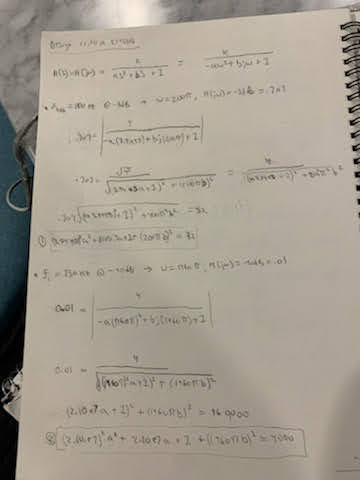
I tried doing some math to figure out a proper circuit
And more math
But failed
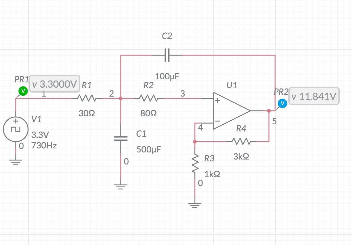
One circuit
Another circuit
Another circuit
Some transistors, MOSFETs, and many circuits later and I eventually was able
to program a circuit using an Arduino microprocessor to move the needle in the
gauges! Exciting. However, when I added a second circuit for the
other gauge, all the calibration was off. Then, when I tried to
illuminate the dash lights it was all off again. The circuit is too
sensitive to fluctuations in voltage and resistance in the car's electrical
system. This is because my circuit is running in "open loop" but I don't
know how to fix it.
The videos above show how I can digitally control one gauge at a time, moving
from empty (or cold), through 1/4 increments to full (or hot).
Plan C - Stepper motors.
Building a digital circuit to mimic the analog sending units proved beyond my
meager electronics ability so I resorted to the modern approach -- replacing
the guts of the gauges with stepper motors. This is how modern car
gauges operate. The stepper motors are small, precise, low torque motors
that can be easily controlled from a computer in increments as small as half a
degree of rotation. The X27.168 motors I am using have a total sweep of
315 degrees with 600 steps, or 1.9 steps per degree. This is plenty of
arc and precision for smooth gauge operation. The motors have internal
gearing but are extremely low torque -- only powerful enough to move something
very light, such as a gauge needle. The motors aren't super fast either
- about 1 second for a full sweep - but they're fast enough for vehicle or
engine speed and range and temps don't change quickly so, in this case, speed
doesn't even matter.
The first step is to disassemble the original VDO gauges, removing the gauge
itself, then removing the needle and gauge face from the gauge guts.
The original fuel gauge
The original gauge blown apart
The second step is to design a mount that will support the face, the stepper
motor, and the needle and allow mounting back into the original gauge
housing. This is were Computer Aided Design (CAD) and 3D printing come
in handy. I designed and printed a two piece mount that has a recess to
hold the stepper motor and screw holes for attaching the face. This is
covered by a spacer plate that allows for the electrical connections and has
holes for attaching to the original gauge backing plate. I printed it in
clear PLA and left a space for light to come through from the original bulb
location.
CAD model of stepper motor mount and spacer
The stepper motor installed in the 3d printed mount
Stepper motor mounted in clear 3d printed housing with room for light
Original gauge face mounted to stepper motor
Steppers all wired up nice and clean
The next step is attaching the needle. The shafts on the VDO gauges are
much smaller in diameter than than the shafts on the stepper motors so the
needle won't press on. The solution was to print a small disc that has
an interference fit over the stepper motor shaft and then glue the needle to
that disc.
Shaft on original gauge (left) is much smaller than on stepper motor
(right) making needle installation a PITA
Time to build a controller circuit and program the motors. There are a
number of chips available for controlling stepper motors, such as AX1201728SG
quad drivers, or
L293D
or
TB6612 dual-channel H-Bridge motor drivers. I opted for the TB6612 chip
because all the chips are surface mount and that ship was available in a
pre-mounted board configuration from Adafruit with polarity protection
FET on the motor voltage input and a pullup on the "standby" enable pin.
There are a few different Arduino libraries for working with steppers. I
used one called
SwitecX25
because it offers good asynchronous control, which I need in order to move
both gauges at the same time. The basic code is silly simple. It
gets slightly more complex with CANbus integration but is still quite easy.
Simple circuit using an Arduino MKR Zero and two TB6612 driver chips
The hardest part of the whole process is attaching the original
needles. I'm still working on that. Using paper needles in the
meantime. See it operational with a sample program that just moves between
min/half/max values below.
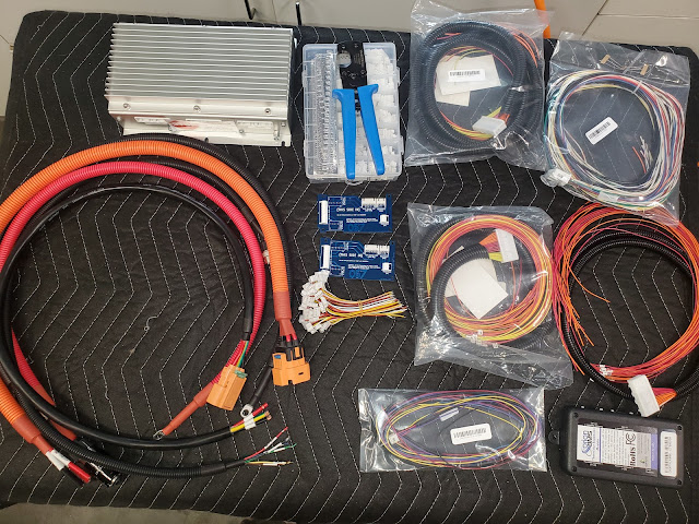
Building a box to hold batteries sounds so simple. It isn't. The batteries have been in and out of my front box many times now. The latest reasons for disassembly were to relocate the BMS and plate the buss bars . While plating, we decided to do the buss bars in Paul's car also since the battery box is out of the car while the car is being painted. My box on the left, Paul's on the right It is interesting to see the two approaches to battery fitment side by side. Figuring out how to get 14 Tesla Model S battery modules fitted into a car designed for a gas engine and transmission is always the most difficult part of the EV conversion process. The big rectangular batteries just don't want to fit into the curvy voids of a normal car body.
As mentioned previously, careless treatment of the Tesla battery modules can be catastrophic, leading to fire or other failure. Therefore, it is important to monitor the state of the cells to assure they are in proper temperature and charge or discharge. To do this, a Battery Management System (BMS) is required. I'm using the popular Orion BMS 2. The BMS protects and monitors a battery pack by monitoring several sensors and using several outputs to control charge and discharge into the battery. The BMS measures inputs from cell voltage taps, a hall effect current sensor, and thermistors. Using the programmed settings, the BMS then controls the flow of current into and out of the battery pack by broadcasting charge and discharge current limits via the CANBUS to the OnBoard Charger (OBC). During and immediately after charging, the BMS will balance the cells using internal shunt resistors based on the programmed settings.


